
.png?x-oss-process=image/resize,h_3000,m_lfit/format,webp)
In grinding operations, vibration is rarely “just noise.” It is usually a measurable signal that something in the wheel–spindle–workholding system is misaligned, unbalanced, or running outside its stable cutting window. When vibration is reduced, surface finish improves, size control becomes more predictable, and wheel life typically extends—often by 15–30% in real production settings.
Wheel imbalance creates a cyclic force that grows rapidly with speed. Even small mass errors on a large-diameter wheel can generate spindle loads that show up as chatter marks, taper, thermal damage, and inconsistent stock removal. As a rule of thumb, many plants target a vibration velocity of ≤ 1.8 mm/s RMS at the wheelhead for stable finishing; roughing may tolerate higher, but rising trends are an early warning.
.png)
Balancing can only work if the wheel is mounted correctly. Many vibration problems blamed on “machine rigidity” are actually caused by mounting errors: dirty flanges, distorted blotters, incorrect torque, or a runout stack-up between arbor, flange, and wheel bore.
Note: If runout is high, balancing won’t “erase” it. First correct mounting, flange condition, and arbor seating; then balance.
Shops typically choose between static balancing (simple, low cost) and dynamic/in-machine balancing (faster corrections under real operating conditions). For many precision grinding lines, the best results come from combining a good static balance with a quick in-machine trim after dressing.
Static balancing is effective for many wheel sizes and speeds when done carefully. A stable balancing stand and clean arbor journals are non-negotiable.
Dynamic balancing accounts for real spindle behavior, wheel speed, and assembly eccentricities that static balancing may miss. In production, it often pays back quickly when chasing micron-level size control or fine Ra targets.
| Process stage | Typical vibration velocity (RMS) | Common impact if exceeded |
|---|---|---|
| Finishing / sizing | ≤ 1.8 mm/s | Chatter marks, poor Ra, size scatter |
| General production grinding | 1.8–3.5 mm/s | Edge breakdown, dressing frequency rises |
| Aggressive stock removal | 3.5–7.1 mm/s | Higher risk of burns, spindle load instability |
Speed influences chip thickness, heat generation, and dynamic stability. When vibration appears, operators often reduce speed instinctively; sometimes that helps, sometimes it worsens chatter by moving the system into a resonance band. A more reliable approach is controlled testing around a known baseline.
Many shops see immediate improvement by treating speed like a tuning parameter, not a constant. A 10% change can be enough to escape a resonance and stabilize the cut.
Coolant is not just for temperature control—it affects lubrication, swarf evacuation, wheel sharpness, and surface integrity. Poor coolant practice can mimic imbalance by causing wheel loading and intermittent cutting forces.
| Task | Frequency | Simple KPI |
|---|---|---|
| Measure concentration (refractometer) | Daily / per shift | Within target band (e.g., 5–8%) |
| Check nozzle direction and jet coherence | Weekly | No overspray; stable contact-zone flow |
| Filter inspection / replacement | Weekly to monthly | DP/flow within spec |
| Sump cleaning and sludge removal | Quarterly (typ.) | Reduced odor, stable finish, fewer clogs |
Hard and brittle materials punish unstable setups. When vibration is present, the first goal is to reduce force variation: keep the wheel sharp, avoid loading, and use a conservative depth of cut until stability returns. The numbers below are starting references that many shops validate through small DOE trials.
| Material | Common risk | Stable adjustment ideas |
|---|---|---|
| Tungsten carbide | Micro-chipping, chatter lines | Prioritize balance + sharp dressing; reduce DOC by 20–40% if chatter appears; strengthen coolant jet to prevent loading |
| Ceramics | Crack initiation, edge breakout | Use lower force strategy: smaller stepdowns, stable fixturing; verify runout before balancing; keep wheel face true |
| Hardened steel (HRC 55–65) | Burn, tensile stress | Avoid dull wheel: dress more frequently; tune speed in ±5% bands; maintain concentration and filtration to limit scratches |
| Glass / quartz | Brittle fracture, poor edge quality | Reduce vibration first (balance + runout); increase coolant cleanliness; use gentle infeed and consistent contact |
Scenario: A shop running precision grinding on hard materials reported an acceptable finish right after wheel change and balance, but chatter returned after a short production run. Operators repeated balancing with limited improvement.
The key lesson: balancing is necessary, but it cannot compensate for a wheel that becomes dull and loads up. Stability requires a system view—mounting, balance, dressing, and coolant working together.
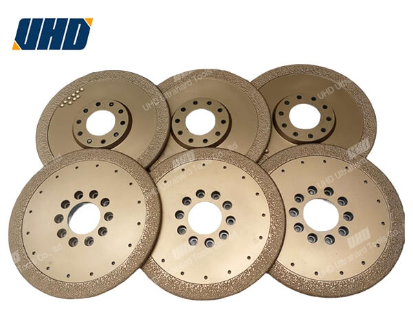
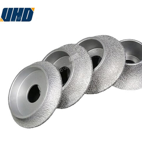
For hard and difficult-to-grind materials, many manufacturers turn to brazed diamond grinding wheels for their aggressive cutting action and strong grain retention. When properly selected and supported with correct operating parameters, they can help reduce unexpected loading behavior and keep the grinding force more consistent—both of which support lower vibration and better accuracy.
Henan UHD (UHD) focuses on high-quality brazed diamond wheels and application-level technical support. For engineering teams, that support often matters as much as the wheel itself: confirming bond/grit choices, matching wheel geometry to the spindle, and recommending dressing/coolant strategies to keep the process stable over long production runs.
Send your material, machine model, wheel size, and current parameters. UHD’s team can help recommend a practical wheel setup and balancing-friendly configuration for your process.
Explore UHD Brazed Diamond Grinding Wheels & Technical SupportA grinding line becomes predictable when vibration is treated like a controllable variable: mount clean, verify runout, balance correctly, keep the wheel sharp, and maintain coolant like a process fluid—not a background utility.
.png?x-oss-process=image/resize,h_800,m_lfit/format,webp)


 Brazed diamond grinding wheels
Industrial grinding impact resistance
Fracture toughness detection
Thermal stability testing
Brazed interface strength
Diamond cutting and grinding wheels
Superhard tools
Industrial cutting solutions
Brazed diamond tools
High - manganese steel substrate wheels
Stainless steel grinding parameters
Gray cast iron grinding techniques
Diamond grinding disc usage guide
Efficient grinding solutions
Industrial material processing optimization
custom diamond grinding wheels
surface grinding solutions
diamond wheel diameter selection
industrial grinding optimization
precision grinding tools
Brazed diamond grinding disc
Heavy - load grinding efficiency
Wear - resistant diamond tools
Stainless steel high - efficiency grinding solution
Industrial - grade grinding disc lifespan improvement
Brazed diamond grinding wheels
Industrial grinding impact resistance
Fracture toughness detection
Thermal stability testing
Brazed interface strength
Diamond cutting and grinding wheels
Superhard tools
Industrial cutting solutions
Brazed diamond tools
High - manganese steel substrate wheels
Stainless steel grinding parameters
Gray cast iron grinding techniques
Diamond grinding disc usage guide
Efficient grinding solutions
Industrial material processing optimization
custom diamond grinding wheels
surface grinding solutions
diamond wheel diameter selection
industrial grinding optimization
precision grinding tools
Brazed diamond grinding disc
Heavy - load grinding efficiency
Wear - resistant diamond tools
Stainless steel high - efficiency grinding solution
Industrial - grade grinding disc lifespan improvement


.png?x-oss-process=image/resize,h_100,m_lfit/format,webp)
.png?x-oss-process=image/resize,h_100,m_lfit/format,webp)
.png?x-oss-process=image/resize,h_100,m_lfit/format,webp)

